| Type |
Werk.Nr |
Registration |
History |
| C19 Mk IV |
122 |
D-2300 |
First flight in Aug. 1932, pilot Commander Brie. Tested by the DVL |
| Type |
Two seat autogyro |
| Engine |
1 Semens Sh 14 |
| Dimensions |
Length 6,92 m , height 2,82 m , rotordia. 10,36 m |
| Weights |
Empty 520 kg, loaded 705 kg , max. take off weight |
| Performance |
Max.. speed 155 km/h , landing speed 35 km/h , range , endurance , service ceiling 2500 m , climb 9 min. to 1000 m |
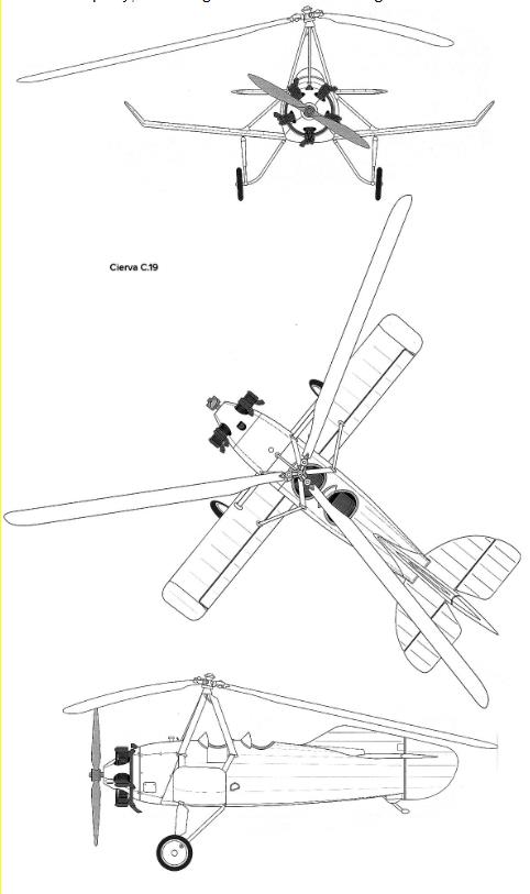
The C.19 is a reconnaissance gyroplane designed by Spanish-born engineer Juan de la Cierva. Sierva made the next important step in the development of gyroplane design with the C19 model in 1929. Previously, the main rotor was spun manually before takeoff. This increased lift and reduced take-off distance. It must be said that all gyroplanes could take off and land on small areas inaccessible to airplanes. But spinning the bulky rotor manually turned out to be a labor-intensive and rather time-consuming operation. On the S19 Mk I they made a rotating tail unit. Before takeoff, this complex box-shaped structure was turned about 90 degrees, so that the air flow from under the tractor rotor was deflected by the tail and hit the rotor blades, causing it to spin itself - autorotation. After the main rotor gained the required speed, the tail was installed in its previous position.
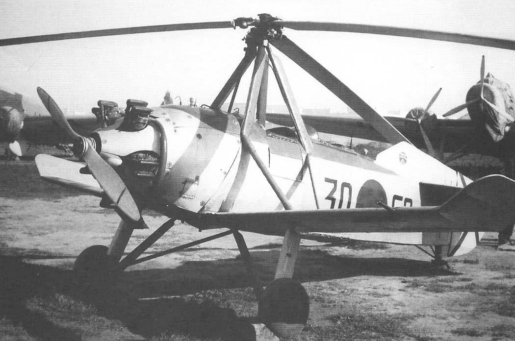
The C19 was already a completely independent design, and not a modification of the aircraft. The fuselage had a frame made of steel pipes, covered in front with duralumin sheets, and covered in fabric at the back. At the front of the fuselage, just like an airplane, there was an engine that rotated a two-blade wooden propeller. The gyroplane had short wings supported on top by braces. Ailerons were mounted on them. The landing gear was typical for aircraft of that time - two main struts in front and a crutch at the rear, inscribed in the contours of the vertical tail. The three-bladed rotor was located at the top of a pyramid formed by four struts - just above the front cockpit. The tail included a small elongated keel, a rudder and a fairly large horizontal tail.
Following Mk I, the slightly different types Mk II and Mk III appeared. The C19 Mk III gyroplane was chosen as the prototype for the experimental gyroplane 2-EA, which was being built at TsAGI. The 2-EA was larger than Sierva’s apparatus and was equipped with a more powerful Gnome-Ron “Titan” engine of 230 hp, but the “scorpion tail” - a biplane stabilizer-deflector was almost completely copied from the English car.
Three years later, Armstrong-Siddley engineers proposed spinning the main rotor directly from the engine. The torque began to be removed from the rear of the engine crankshaft and transmitted to the rotor hub through a reduction gearbox and auxiliary shaft. Engine spin-up was first installed on the C19 Mk IV gyroplane. During testing, the gyroplane was placed against the wind and the brakes on the wheels were applied. Then the main rotor was spun at low throttle. Having reached 180-200 rpm, they released the brakes, turned off the rotor drive and gave full throttle - the gyroplane soared sharply upward.
On this same modification, cantilever blades were introduced for the first time (previously, all gyroplanes had braced blades). Inside the blade there was a steel pipe that absorbed all the loads. Wooden ribs were put on it, which determined the aerodynamic profile. On top they were covered with plywood and canvas with varnish.
Autogyroplanes of the C19 family were built in small series by the Avro company (as the Avro 620 ). A total of 29 of them were produced. The main production version was the C19 Mk IVP with a Janet Major I engine of 105 hp. The Avro plant in Hamble produced 15 of these machines. They were operated in Great Britain, Spain, Germany and Sweden. Two C19 gyroplanes were purchased by the British Air Ministry in 1930-31.
The batch of C.19 Mk.IV gyroplanes, built under license by Focke-Wulf in Germany, had a Siemens Sh.14B radial engine with a power of 112 kW and the designation C.20 of the Sierva company; the designation C.21 was assigned to the C.19 Mk.IV gyroplane, designed in France and built by Liore-et-Olivier (LeO); S.22 and S.23 remained in the projects.