Project from 1920
Flight JUNE 9, 1921
THE DORNIER TWIN-ENGINED MONOPLANE, TYPE G.I
Two 185 H J \ B.M.W. Engines
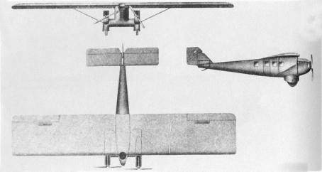
IN our issue of May 9, 1921, we published two photographs of a wind-tunnel model of the Zeppelin-Dornier twin-engined monoplane, Type G.i. Since then further details are to hand relating to this machine. As in previous Dornier aeroplanes and seaplanes, the construction is of metal throughout.
Generally speaking this Dornier resembles previous ones in the shape of its monoplane wing, fuselage, and tail. It differs, however, in that it is provided with two engines placed very low at the outer ends of the usual Dornier wing roots growing out of the lower portion of the fuselage. The latter projects only a short distance in front of the leading edge of the plane, thereby making it possible to bring close together the two engines, which, as a matter of fact, are only sufficiently far apart to prevent their tips touching. Evidently the object of this arrangement is to reduce to a minimum the turning couple set up in case one of the engines stops.
The undercarriage is of the simplest possible type, consisting of one large wheel on each side, placed immediately underneath the engines. The weight of the fuselage with its contents and of a portion of the wing, is transmitted to the wheels by the deep section wing roots, to the ends of which the engines are attached. The wing itself is braced by two tubes of streamline section on each side, supporting the nontapering monoplane, which is of the usual rectangular plan form.
The general construction, as usual in Dornier practice, consists of steel members for all heavily stressed parts, and duralumin for the details taking small loads only, and for the covering.
Owing to the general arrangement of the machine, one imagines that it would be comparatively safe in the case of a crash, as the engines are slightly below and well ahead of the cabin. The petrol tanks are placed inside the wing, one on each side, so as to give gravity feed to the engines, but yet being, it is claimed, sufficiently far removed from them to ensure that no petrol could possibly leak down on to the hot engines.
So far as we are aware, no provision has been made for enabling passengers to get out through the roof, in case the door should be jammed, but if found necessary, this could easily be arranged for in the rear portion of the cabin, where the trailing edge of the wing could be cut away, probably withoub serious loss in aerodynamic efficiency. On the whole, the machine, which is designed to carry eight passengers in addition to the pilot, impresses one as being of rather promising design, and it will be interesting to see how the machine behaves in actual use. The B.M.W. engines have a reputation for reliability and exceptionally economic fuel consumption, and, rating the engines at 200 h.p. each, the machine carries a passenger for each 50 h.p., which should be a fairly economic proposition, especially coupled with the fact that the machine has a cruising speed of over 90 miles per hour.
| Type |
Project for an airliner, capacity 8 - 10 passengers |
| Engine |
2 BMW |
| Dimensions |
Length 12.2 m, height 3,05 m, span 21.0 m, wing area 80 m2 wing chord 4,00 m |
| Weights |
Empty 2350 kg, flying weight 3450 kg fuel consumption 78 kg/h at max. speed, 60 kg at cruising speed, oil 4 kg/h at max. speed, wing loading 4 kg/m2 power loading 9,3 kg/hp |
| Performance |
Max. speed 180 km/h, cruising speed 150 km/h service ceiling 6000 m |
Flight MAY 19, 1921
A NEW ZEPPELIN - DORNIER TWINENGINED
AEROPLANE :
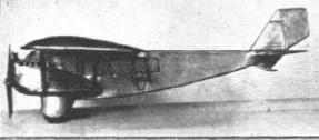
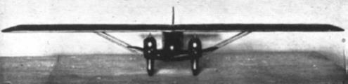
The keen competition between the Friedrichshafen and Staaken Zeppelin works appears to continue. In our issue of March 17 we published a photograph of the wind-tunnel model of a Staaken twin-engined monoplane. Above is seen the model of Herr Claude'Dornier's reply. This machine, it will be seen, has a fuselage practically
identical to that of the single-engined land machine shown in our issue of March 31, 1921, and single-engined flying boat published on April 21, 1921. The new machine is characterised by a very low position of the engines, in fact one would imagine that they are placed too low. They are mounted on the ends of the usual Dornier wing roots growing out of the sides of the fuselage. From the outer lower corners of the engine nacelles bracing tubes run to the monoplane wing. Each of the landing wheels is enclosed in a streamline casing.