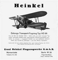
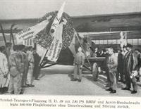
Die ersten 100 000 km eines Zeitungs-Transport-Flugzeuges.
Am 29. März hat ein im täglichen Luftdienst eines großen Berliner Verlages
Hegendes Heinkel-Zeitungstransport-Flugzeiig seinen 100000 Kilometer
zurück- gelegt. Diese außerordentliche Leistung, die ohne Unterbrechung
und nennenswerte Störung vollbracht wurde und die deshalb als bahn-
brechend für den Eildienst-Lastentransport der Zukunft angesehen werden
darf, verdient um so höhere Anerkennung, als es sich hier um den ersten
Versuch einer Privatfirma handelt, ihre Leistungsfähigkeit und Rentabilität
durch Einstellung eigener Flugzeuge zu erhöhen. Nach den mit dem
Heinkel-Hugzeug gemachten Erfahrungen hat dieser Versuch die
Erwartungen nicht nur voll erfüllt, sondern sogar weit übertreffen.
Taglich und auf die Minute übernahm dieses Flugzeug im Zentralflughafen
Tempelhof seine schwere Zeitungslast, brachte sie in kürzester Zeit nach
oft entlegenen Provinzstädten und kehrte ebenso pünktlich zum Flughafen
zurück. Auf diese Weise wurden in bisher 11 Monaten Flugdienst insgesamt
85 400 kg Zeitungen, das sind ca. 1308200 Exemplare, befördert und
hierbei - wie schon erwähnt - insgesamt 100000 Flugkilometer zurückgelegt. Es
ist dies auf seinem Gebiet eine Weltrekordleistung, die wiederum einen
überzeugenden Beweis für die hohe Leistung und Betriebssicherheit nicht
nur des Flugzeuges, sondern auch des eingebauten BMW IV-Motors
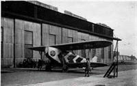
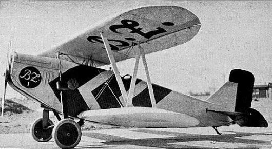
darstellt. Hinzugefügt sei noch, daß dieses Heinkel-Flugzeug, Typ H.D.39, als normaler Doppeldecker gebaut ist und eine Normal-Nutzlast von 400 kg mit einer Horizontalgeschwindigkeit von 166 km/Std. zu befördern vermag.
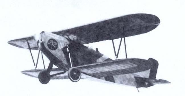
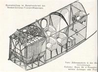
Heinkel Zeitungstransportflugzeuge.
Das Flugzeug H D39 hat vor einiger Zeit seinen 100000ten Flug-kilometer ohne Störung zurückgelegt (siehe Flugsport Heft 8, S. 160). Nachdem sich das Baumuster, wie vorstehender Erfolg zeigt, sehr gut bewährt hat, beabsichtigt Heinkel. denselben weiterzuentwickeln. In aller Kürze wird daher ein neuer Zeitungstransport-Typ im Flugbetrieb erscheinen, der statt bisher 230 PS nunmehr 500 PS hat und bei 4 Stunden Flugzeit eine Zeitungslast von 1000 kg trauen wird.
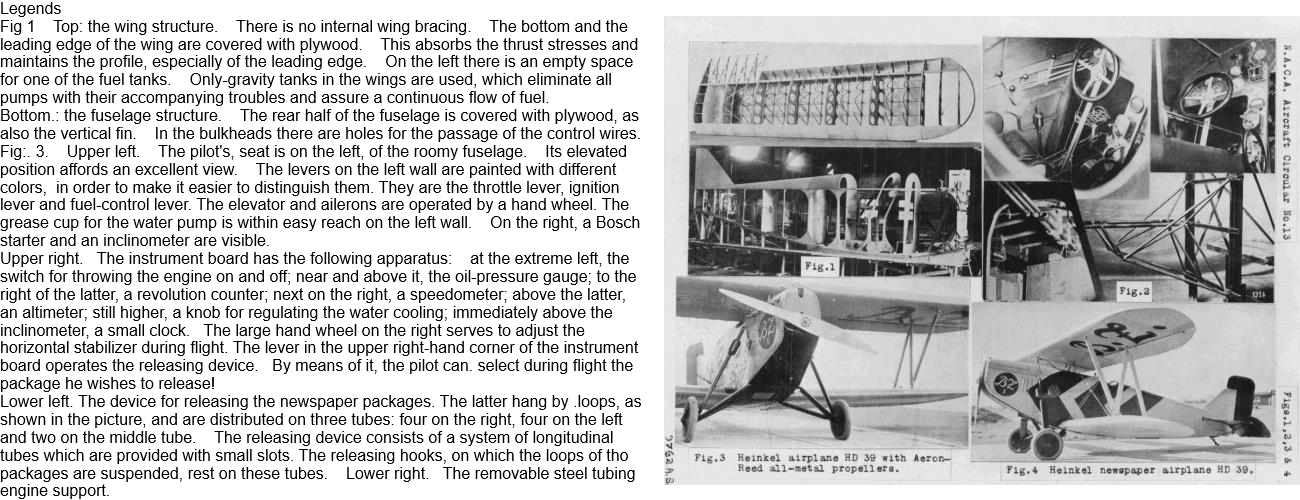
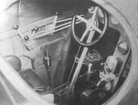
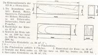
Die vorstehende Abbildung läßt die Raumeinteilung der HD 39 erkennen. Vorn befinden sich in den Abwurfvorrichtungen Zeitungspakete. Dahinter ein weiterer Raum für Passagiere, Zeitungen oder Fracht. Für den Ueberseetranspoit wird diese Maschine in verhältnismäßig kleinen Kisten verpackt. Für die internationalen Interessenten dürften diese Kistenmaße, welche aus obenstehender Abbildung hervorgehen, nützlich sein.
| Type |
1-2 seat aircraft designed for transport of newspapers |
| Engine |
1 BMW IV |
| Dimensions |
Length 10,0 m, height 3,7 m, span 14,8 m, wing area 51,0 m2 |
| Weights |
Empty 1250 kg, crew 170 kg, fuel 230 kg, pay load 400 kg, flying weight 2050 kg, wing loading 39 kg/m2, power loading 8,8 kg/hp |
| Performance |
Speed 160 - 170 km/h, landing speed 72 km/h, climb to 1000 m 7 min., range 800 km |
| Type |
Werk.Nr |
Registration |
History |
|
|
|
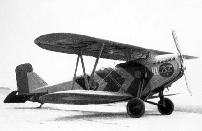
Bz 1. HD 39 entered service in April 1926 by the Ullstein-Verlag and remained in Service until 1931, when distribution of B.Z. by air was taken over by Deutsche Luft Hansa. Shown at the Luftfahrt-Sammlung in Berlin- |