| Type |
R III Civil 2 + 10 seat flying boat or
Military 3 - 4 seat reconnaissance |
R IIIa Military 3 - 4 seat
reconnaissance flying boat |
R 2 (Japanese) |
R 3 (Japanese) |
| Engine |
2 Rolls-Royce Eagle IX |
2 Lorraine-Dietrich |
|
|
| Dimensions |
Length 17.20 m,height 6.00 m, span
29.00 m, wing area 73.40 m2, aspect ratio 11.46 |
Length 17.20 m,height 6.00 m, span
27.55 m, wing area 73.40 m2, aspect ratio 10.34 |
2 Hispano Suiza |
2 Lorraine-Dietrich |
| Weights |
Empty 3600 kg, fuel 1000 kg, oli 80
kg, crew 160 kg, pay load 1460 kg, load 2700 kg, flying weight 6300 kg |
Empty 4680 kg, fuel 780 kg, oli 60 kg, crew 160 kg, pay load 1010 kg, load 2010 kg, flying weight 6690 kg |
|
|
| Performance |
Max. speed 175 km/h at sea level, ,
cruising speed 160 km/h at sea level, climb 2 m/sec., range 1440 km, endurance 9 h, service ceiling 4000 m, landing speed 112 km/h |
Max. speed 185 km/h at sea level, ,
cruising speed 170 km/h at sea level, climb 2 m/sec., range 850 km,
endurance 5 h, service ceiling 3000
m, landing speed 110 km/h |
|
|
| Type |
Werk.Nr |
Registration |
History |
| R2 |
A |
J-BHAE |
Delivered to Mitsubishi 1927 as Mitsubishi Experimental Type R 2. After testing given to Nippon Koku KK in
Sept. 1927 together with the R 1.Before it got Rolls-Royce Eagle engines.Bad experiences when testing led to the R 3 |
| R3 |
|
|
Built from parts from Germany at Hiro Naval Arsenal . Modifications compared to R 2 made a real improvement |
| Ro IIIa |
13 |
1201 |
"Istambul". Delivered to Turkey The plane served at the 1st and 3rd Dz. Ty Bl (Seaplane Co.) and in 1928 it
was transferred to the 31st Dz.Ty.Bl. It was written off in 1934. |
| Ro IIIa |
14 |
1202 |
"Izmir". Delivered to Turkey .The plane served at the 1st and 3rd Dz. Ty Bl (Seaplane Co.) and in 1928 it was
transferred to the 31st Dz.Ty.Bl. It was written off in 1934. |


Das Rohrbach-Flugboot Type Ro. III.
Ueber den Rahmen der bisherigen Veröffentlichung hinausgehend, soll an dieser Stelle eine ausführliche Beschreibung des Rohrbach-Flugbootes Type Ro. III folgen.
In seinem, im Jahre 1922 anläßlich der W. G. L.-Tagung in Bremen gehaltenen Vortrag hat Dr.-Ing. Rohrbach nachgewiesen, daß die
Entwicklung des wirtschaftlichen Großflugzeuges zu einer Erhöhung der Flächenbelastung mit zunehmender Flugzeuggröße führt. Die durch die höhere Flächenbelastung
bedingte, kleinere Flügelfläche hat gleichzeitig eine Verringerung aller übrigen Abmessungen des Flugwerkes zur Folge. Dementsprechend steigt der Gewichtsanteil des
Flugwerks mit zunehmender Flugzeuggröße wesentlich langsamer, als bei gleichbleibender Flächenbelastung, und der Anteil der zahlenden Nutzlast erreicht höhere Werte.
Wie weit man durch diesen neuen eingeschlagenen Weg die überhaupt mögliche Nutzlast steigern kann, läßt sich vorläufig noch nicht mit Bestimmtheit angeben, da
Kraftanlage und konstruktive Durchbildung des Flugwerks noch nicht bis an die Grenze der möglichsten Gewichtsersparnis entwickelt sind. Nach dem bisher Erreichten zu
urteilen, liegt die Grenze etwa bei einem Flugzeug-Vollgewicht von 16 tons, während bei gleichbleibender Flächenbelastung unter den gleichen Konstruktionsvoraussetzungen
die Grenze schon bei etwa 9 tons Vollgewicht erreicht ist.
Neben dem eben besprochenen Vorteil der höheren Flächenbelastung fallen noch weitere zu deren Gunsten in die Wagschale. Da sind zu erwähnen: die größere Wendigkeit,
leichtere Steuerbarkeit und größere Unempfindlichkeit im Fluge gegen Störung durch Witterungseinflüsse. Im Hinblick auf die Wendigkeit hat Dr. Rohrbach in dem oben
erwähnten Vortrage ausgeführt, daß bei Großflugzeugen die notwendige Wendezeit für einen vollen Kreis bei geringer Flächenbelastung stark mit der Flugzeuggröße zunimmt,
dagegen bei Erhöhung der Flächenbelastung nur langsam wächst. Die leichtere Steuerbarkeit leuchtete ohne weiteres aus den kleineren Flugabmessungen ein.
Der in Kauf nehmende Nachteil der höheren Flächenbelastung, die höhere Landegeschwindigkeit, ist vor allem eine Flugplatzfrage, während die Schwierigkeit der Landung als
unmittelbare Folge der höheren Geschwindigkeit wohl durch Schulung des Führers zu meistern ist. Beim Großflugboot das als Hochseeflugzeug stets große Landeplätze zur
Verfügung hat, fällt also der Nachteil der hohen Landegeschwindigkeit nicht ins Gewicht.
Diese Leitgedanken verfolgend, hat die Rohrbach Metall-Flugzeugbau G. m. b. H., Berlin, das Flugboot Ro. III entwickelt. Die Erfolge dieses Typs haben die Erwartungen
vollauf erfüllt. Die Abmessungen, Leistungs- und Gewichtsdaten sind folgende:
10 Sitzer-Limousine
2 Motoren Rolls-Royce „Eagle IX" 2X360 PS.
Gesamtlänge 17,2 m, Spannweite 29 m, Tragfläche 73,4 m2,
Leergewicht 3 600 kg Nutzlast 2 400 kg
Betriebsstoff
für 2 Flugstunden 300 kg
Ges. Gewicht 6300 kg
Flächenbelastung 85,8 kg/m2
Leistungsbelastung 8,75 kg/PS
Geschwindigkeit am Boden 200 km p. Std. Steigfähigkeit 1500 m/13 Min.
Gipfelhöhe 4000 m
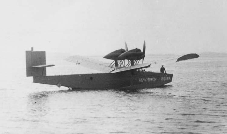
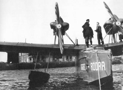
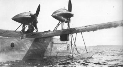
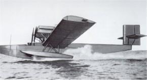
Bei Betrachtung des Flugbootes fällt zunächst die eigenartige Lage der beiden Motoren auf. Für die Anordnung waren maßgebend gute Manövrierfähigkeit auf dem Wasser
und gutes Fliegen mit einem Motor. Die beiden Rolls-Royce „Eagle IX"-Motoren sind daher, wie aus den Abbildungen" ersichtlich ist, auf Böcken aus Stahlrohrprofilen
nebeneinander frei auf dem Flügel gelagert, um die Propeller genügend hoch über dem Wasser zu haben. Die Anordnung der Motoren nebeneinander hat für das Manövrieren
auf dem Wasser den Vorteil, daß durch Gasgeben auf einen Motor ein für ein schnelles Wenden genügend starkes Drehmoment erzeugt werden kann, während bei der
Anordnung der Motoren hintereinander das Flugboot zum schnellen Wenden erst größere Fahrt aufnehmen müßte. Das hat die Folge, daß bei schwerer See mehr Wasser
übernommen wird, und ein Manövrieren in belebten Häfen und Wasserstraßen schwieriger wird. Wie die Flugversuche gezeigt haben, ist trotz der Nebeneinander-An Ordnunc
der Motoren bei Ausfall eines Motors Kurshalten und Kurven gegen den laufenden Motor dank der zweckmäßigen Ausbildung des Seitenleitwerks leicht möglich.
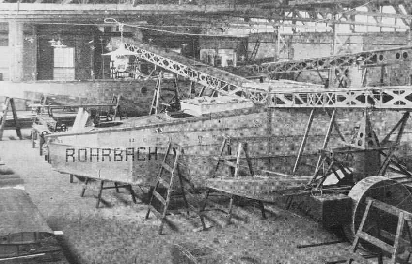
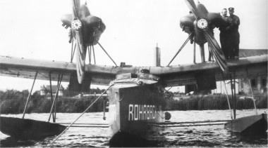
Ein weiteres Merkmal der Rohrbach-Bauart ist der schmale Bootskörper. Die geringe Bootsbreite bedeutet gerade bei einem Flugzeug mit hoher Flächenbelastung, bei dem
die Bodenbeanspruchungen durch Wasserdruck infolge der großen Abfinggeschwindigkeit ganz ungewöhnlich hoch sind, eine sehr erhebliche Ersparnis an Gewicht der Bodenaussteifungen. Mit einem breiten Boot wäre das Gewicht aller mit Rücksicht auf Wasserbeanspruchungen zu bemessenden Teile so groß geworden, daß der größte Teil des durch die hohe Flächenbelastung am Flügel ersparten Gewichtes wieder verloren gegangen wäre.
Der konstruktive Aufbau des Bootes ist sehr einfach. Die Außenhaut ist durch innen aufgenietete Profile so ausgesteift, daß sie mit den Profilen zusammen alle
Beanspruchungen übertragen kann. Ferner ist durch Schotteinteilung volle Schwimmfähigkeit gewährleistet, auch wenn zwei Abteilungen gleichzeitig leck sind.
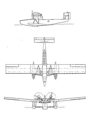
Die von der Hochseefähigkeit geforderte Querstabilität wird durch zwei neben dem Rumpf angeordnete Seitenschwimmer erreicht. Durch diese Steitenschwimmer werden die
Vorteile des Flugbootes, wie sie bisher bekannt waren, mit denen des normalen Zwei-Schwimmer-Flugzuges gewissermassen vereinigt.
Die Schwimmer sind ebenfalls in wasserdichte Abteilungen unterteilt. Diese Unterteilung wurde vorgesehen, um auch bei einem beschädigten Schwimmer einen Start
gefahrlos zu machen.
Die Schwimmer sind durch zwei Stahlrohrstreben seitlich nach dem Flugboot und vier weitere Streben nach oben zum Flügel abgestützt.
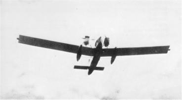
Die Flügelanordnung hat die ungewöhnlich große V-Stellung von 6 Grad. Diese große V-Stellung erschien zunächst bei einer so großen und neuartigen Metallmaschine als ein
gewisses Wagnis, da alle neueren Maschinen keine oder nur sehr geringe V-Stellung aufzuweisen hatten. Die V-Stellung ist aber einerseits mit Rücksicht auf die Seefähigkeit
sehr erwünscht, da sie die Flügelenden hoch über Wasser bringt, und andererseits führt sie zu einer wesentlichen Verbesserung der Flugeigenschaften. Tatsächlich zeigte die
Maschine bei den Probeflügen hervorragende Flugeigenschaften bezl. Wendigkeit und Steuerbarkeit, z. B. geht sie sehr leicht allein durch Betätigung des Seitenruders, unter
Loslassung der übrigen Steuer in die Kurve und ebenso kann sie allein durch Betätigung des Seitenruders wieder in den Geradeausflug gebracht werden.
Der ganz aus Duralumin erbaute Flügel besteht aus drei Hauptteilen: dem alle Beanspruchungen aufnehmenden Hohlkastenträger, und den beiden vorn und hinten an ihn nur zur Formgebung angesetzten äußerst leichten Nasen- und Endstücken. Diese Nasen- und Endstücke sind in üblicher Weise durch Rippen versteift und mit dünnem Blech überzogen. Der Hohlkastenträger wird durch zwei Längsstege und mit diesen durch längslaufende Winkel verbundene Ober- und Unterhautbleche gebildet. Querwände, die mit Ober- und Unterhaut, sowie mit den Stegen vernietet sind, sichern die richtige Querschnittform des ganzen Kastenträgers. Die Längsstege werden so ausgespart, daß nur die notwendigen Diagonalen und Pfosten vorhanden sind. Die Hautbleche werden durch aufgenietete Profile vor örtlichem Zusammenknicken bewahrt. Da außerdem bei diesem Hohlkastenträger alle Materialquerschnitte sehr weit außen liegen, alle Teile ein festeres Ganzes bilden, als bei anderen Holrnbauarten, so dürfte es klar sein, daß der Flügel so leicht wird, daß man ihn ganz freitragend mit ^Seitenverhältnis 1:10 bauen kann, bei einer Festigkeit, wie sie für Schleifenflug und Rolling erforderlich ist.
Bei den steilen Sturzflügen und Kurven, die mit dem Rohrbad; Flugboot ausgeführt wurden, zeigte der Flügel nicht die geringste Neigung zu flattern oder auch nur in Teilen zu
erzittern.
Da ferner der Flügel vollkommen aus Duralumin gebaut ist und nur die zum Zusammenbau des ganzen Flugzeuges dienenden Hauptbeschläge aus Stahl bestehen, ist er
weniger durch Korrosion gefährdet, als irgend eine andere Flügelart. Zum vollständigen Schutz gegen Korrosion werden alle Teile innen und außen mit Lack gut gestrichen.
Die aufklappbaren Nasen- und Endkästen (Siehe die Abb. 2) ermöglichen im Betriebe ein leichtes Nachsehen aller Teile des Flügels, und wenn erforderlich, einen neuen
Anstrich mit Schutzfarbe. Das Abnehmen der Nasen- und Endkästen erfolgt durch Lösen einiger außen freiliegenden Schrauben. Der Vorteil, der in der Abnehmbarkeit der
Nasen- und Endkästen liegt, wird noch dadurch gesteigert, daß diese in unter sich gleiche, von einander unabhängige Abschnitte unterteilt sind. Bei Beschädigungen von
Nasen- und Endkästen können daher diese leicht durch auf-Lager gehaltene Teile ausgewechselt werden.
Für das Zuwasser- und Anlandbringen des Flugzeuges ist eine besondere Bergungseinrichtung vorgesehen. Es werden zu beiden Seiten des Bootes an dem Flügel
Bergungswagen befestigt. Das Ansetzen und Abnehmen der Bergungswagen kann leicht von zwei ungelernten Arbeitern in 4 Minuten erledigt werden. Das Flugzeug rollt auf
diesen Bergungswagen aus der an Land befindlichen Halle mit eigener Kraft ins Wasser und umgekehrt auch wieder ans Land.
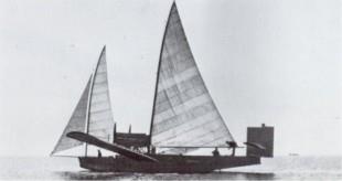
Ferner soll noch erwähnt werden, daß das Rohrbach-Flugboot auch mit einer bereits erprobten Besegelung (vergl. Abb. 3) ausgerüstet werden kann. Die an sich durch die
Verwendung von zwei Motoren erhöhte Betriebssicherheit wird durch diese Segelausrüstung noch weiter gesteigert, da das Flugboot in der Lage ist, bei Versagen beider
Motoren als Segelschiff seinen Weg fortzusetzen.