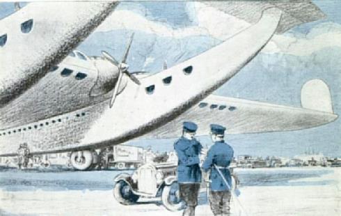
Type Project for a Canard Passengercarrying plane , crew 10 + 100 passengers
Engine 4 1000 hp
Dimensions Length 24,00 m, height 7,50 m, span 80,00 m, wing area  600 m2, max. wing chord 10,00 m, max. height of the wing profile 2,30 m
Weights Empty 14000 kg, flying weight with 100 passengers and luggage (12000 kg) 36000 kg, fuel capacity for ten hours flight 10000 kg, wing loading 60
kg/m2, spec. load capacity 9 kg/hp
Performance Max.. speed 100 km/h , cruising speed  , range , endurance  , service ceiling   , climb
Luftfahrt International 22
The "Future Monoplane"
Junkers J. 1000
In connection with the reappearance of a J. 1000 model, presumably from the so-called Junkers educational display and soon to be exhibited again at the Deutsches Museum
in Munich, this highly interesting project deserves further attention.

The J. 1000, a canard-type aircraft in which Hugo Junkers' proposal for a thick, load-bearing wing, developed in his well-known glider patent, was to be largely realized, represented the provisional culmination of a development of a series of remarkable Junkers large and giant aircraft that had begun in World War I and was halted in the post-war years by the Treaty of Versailles. The project was briefly mentioned in earlier articles (Vol. I. No. 14, pp. 2137 ff., No. 18, pp. 2810 ff.).
The aircraft, which contrary to other accounts was not presented to the public in 1925, but a year earlier at the 63rd General Meeting of the VDI in Hanover, was intended to transport 100 passengers along with luggage (12,000 kg), 10 crew members, and fuel for 10 hours of flight time (10,000 kg).
The occasionally used term "transoceanic aircraft of the future" was certainly inaccurate, because with a maximum flight duration of 10 hours and an airspeed of 190 km/h, the aircraft would not have been able to cross the Atlantic even from west to east at its narrowest point and without a sufficient fuel reserve. Nevertheless, this design, which in its first version was presented only five years after the end of World War I, represented an enormous advance compared to foreign designs, not only because of its huge dimensions, but also because of its entire conception.

Besides the use of a very thick, cantilevered wing, in which all cabins, baggage and crew compartments, fuel and engines were to be housed, the use of retractable landing gear and a novel engine system is noteworthy. The landing gear was to retract into the two fuselages, and the landing gear bay was to be covered at the bottom by a kind of louver. To be able to land with the landing gear retracted in the event of an emergency landing, the underside of each fuselage was reinforced by a robust skid. For the engine system, which was initially intended to produce 4 x 1000 hp = 4000 hp, a novel solution had been found: for the first time in aircraft construction, free-piston compressors were to be used. The compressed air generated by the compressors was first conveyed via special pipes to a collection tank and from there to the turbines located behind the propellers. A three-view drawing of the J. 1000, illustrated in issue 18 on page 2811, shows the course of the pipe system from the engines to the turbines in the top view of the left wing.

Over time, the project was apparently revised and modified several times. At a later date, a different and more powerful engine system is reported: four 2000 hp diesel engines were to be installed directly in front of the wing nose in place of the turbines. The aircraft's overall appearance would hardly have been affected by this, but its performance would have improved considerably. The J. 1000 remained a project, but nevertheless provided such a wealth of inspiration that it likely had a significant influence on aircraft construction.

Construction Description "Future Single-Plane" Junkers J. 1000
Four-engine canard airliner, 1924.
Flying Structure
Tube frame with corrugated metal skin. Command post above the wing nose with good all-around visibility. Behind it, the flight crew room and galley. Next to the command post, a cabin for the captain and first officer, or for two pilots. Behind these rooms are the engine rooms with free-piston compressors. All passenger compartments are located in the wing, which is 2.3 m high at its thickest point. There are 12 cabins for 6 people each in the forward section, and 14 further cabins for 2 people each in the central aisle of the wing. All passenger seats are designed for quick conversion into sleeping berths (like in railway compartments). There is also sufficient space for crew and baggage compartments.
Fuselage Structure
Two short fuselages, constructed like the flying structure, connect the flying structure to The forward wings serve as dining and observation areas for 18 people each and contain the landing gear bay for the main landing gear.
Landing Gear
Two main landing gear assemblies, each with three wheels side-by-side, retractable into the fuselages, covered by a louver. Two fixed tail skids with rollers.
Wings
Forward wings designed as all-moving horizontal stabilizers. Twin vertical stabilizers arranged as extensions of the two fuselages. In addition, two keeled, angled (rudderless) fins are arranged near the wingtips (only on the upper surface).

Engine
Originally, 4 x 1000 hp = 4000 hp free-piston compressors were planned, which, via a piping system, a collection tank, and a subsequent second piping system, supplied the four turbines located behind the propellers with compressed air. Later, 4 x 2000 hp = 8000 hp was specified as the engine output; the oil-lubricated engines were to be arranged in the conventional manner directly behind the propellers in the wing nose.